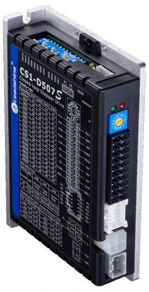
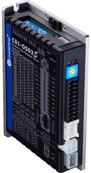
Difference between revisions of "Leadshine CS1-D507S Closed Loop Stepper Drive"
Jump to navigation
Jump to search
(initial page creation) |
(No difference)
|
Revision as of 08:33, 20 August 2022
Overview
Closed loop stepper drives made by Leadshine. They output/repeat encoder signals for the control system, making them appear as servo drives. It supports connecting to a PC via RS-232 for configuration/diagnostics.
Wiring Diagram
- Page 8 (4 in the PDF) shows the names/locations of the various connectors, switches, and LEDs
- Page 8 (4 in the PDF) shows the control connector
- Page 8 (4 in the PDF) shows the control connector pinout
- Page 10 (6 in the PDF) shows the encoder connector pinout
- Page 10 (6 in the PDF) shows the motor output connector pinout
- Page 10 (6 in the PDF) shows the power input connector pinout
- Page 11 (7 in the PDF) shows the RS-232 connector pinout
- Page 17 (13 in the PDF) shows example step/direction/enable/reset wiring
- Page 18 (14 in the PDF) shows example alarm/feedback wiring
Switch Settings
- Page 11 (7 in the PDF) gives an overview of the switches
- Page 13 (9 in the PDF) shows the "S1" rotary switch settings
- Page 14 (10 in the PDF) shows the "S2" DIP switch settings
- Page 16 (12 in the PDF) shows the "S3" voltage level selector switch
Dimensions
- Page 7 (3 in the PDF) shows the drive's dimensions
Fault Codes
- Page 19 (15 in the PDF) shows the LED blink fault codes
Replacement Parts
RS-232 Cable
CABLE-PC-1
CABLE-PC-1 Tune Cable | Leadshine.com
Online Resources
CS1-D507S Closed Loop Stepper Drive | Leadshine.com
CS1-D503S Closed Loop Stepper Drive | Leadshine.com
Leadshine CS1-D507S Closed Loop Stepper Drive User Manual (V1.1, Mar 2020)
Leadshine CS1-D503S Closed Loop Stepper Drive User Manual (V1.1, Mar 2020)
Leadshine CS1-D507S & CS1-D503S Closed Loop Stepper Drive User Manual (V1.01, Nov 2019)

